Digital Controller Pre-Programming
SYSTEM INFORMATION
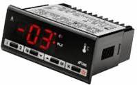
The DC-1 controller supplied with all US Cellars Wine Cellar Cooling equipment is programmed to operate with a 5 °F differential in air temperature. The pre-programmed system controls for the run time of the equipment help to balance the humidity of the wine cellar.
If the factory controller is replaced, the replacement should have a deferential that can be adjusted from 1 °F to 10 °F.
If the alternate controller does not have this ability, US Cellars cannot assure proper operation of the wine cellar refrigeration system.
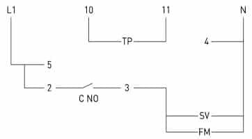
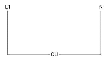
Field Wiring
L1115V Line Voltage
NNeutral
SVSolenoid Valve
FMFan Motor
TPTemperature Probe
Back of Controller Connections
10Temperature Probe
11Temperature Probe
4Neutral
5115V Line Voltage
2Jumper from 5
3Switch Leg to Fan Coil
C NOInternal normally open contact
| Parameter Name | Parameter Setting | Parameter Description |
| SCL | F | Temperature scale is in degrees F |
| SPL | 40F | Lowest allowable set-point |
| SPH | 70F | Highest allowable set-point |
| SP | 55F | The control set-point ( turn off ) |
| C-H | REF | Controller set to operate a refrigeration cycle |
| HYS | 5 | The control differential (cut in set-point of 60F, will maintain a 57F target) |
| CRT | 10 | Minimum compressor rest time after cycling off |
| CT1 | 15 | Compressor “ON” time when the temperature sensor fails (in minutes) |
| CT2 | 15 | Compressor “Off” time when the temperature sensor fails (in minutes) |
| CSD | 0 | A compressor stop delay after the door has been opened. (not applicable, set to 0) |
| DFR | 1 | Defrost per day |
| DLI | 60 | Defrost termination temperature |
| DTO | 30 | Defrost duration in minutes |
| DTY | ELE | Defrost Type, ELE = Electric Defrost (this my assumption, “GAS” = Hot Gas defrost, and this will force the compressor on) |
| DDY | 10 | This feature enables the controller to display “REC” for “x” number of minutes after the defrost has expired and the refrigeration has resumed. (I suggest 15 minutes) “DEF” will be displayed during the defrost cycle. |
| ATM | REL | Alarm function is active and the high & low alarm set-points are independent temperature values. |
| ALR | -10 | Low alarm set-point ( I would suggest -25F) |
| AHR | 10 | High alarm set-point (I would suggest -5F) |
| ATD | 120 | Alarm delay in minutes (I would suggest 30 minutes) |
| ADO | 0 | Alarm delay for an open door (not applicable if a door switch is not used) |
| ACC | 0 | This parameter will trigger an alarm after a defined number of weeks has expired for the compressor operation. For example, the ACC parameter is set to “1”, then every 168 hours of compressor operation will trigger this maintenance alarm. This is a good feature for cases that require condenser coil cleaning. Set this feature to “0” to disable it. |
| SB | YES | When this parameter is set to “YES”, the controller operation can be put in standby mode by holding in the key on the far right of the keypad. In standby mode, all relays cycle off. This works well for maintenance work but can pose problems if it is misused. Setting this parameter to “NO” will disable the feature. |
| DS | NO | This feature enables the door switch input. The “NO” setting disables this feature. |
| OAU | NON | This parameter defines the function of the “AUX” relay (the second relay on the controller). “DEF” defines the relay as you defrost relay. |
| INP | SN4 | This parameter defines the type of temperature sensor used. “SN4” is the sensor type of the standard 10K NTC sensor. This will always be your choice. |
| OS1 | 0 | The offset for sensor one (“T1”). Should not require adjustment. |
| T2 | NO | This parameter enables the “T2” defrost termination sensor. |
| OS2 | 0 | The offset for sensor one (“T2”). Should not require adjustment. |
| TLD | 5 | Your LAE controller is set up to log the historical high & low-temperature extremes of your control temperature sensor. This delay parameter (in minutes) requires your high or low temperature reading to last for 5 minutes or longer before it is logged. You can view the “THI” (high temp) and “THO” (low temp) by pressing the “I” button on the controller’s keypad. The “I” button is the “info” button. It is the key located to the far left of the controller’s keypad. |
| SIM | 0 | The “SIM” function slows down the rate of change in the temperature displayed on the controller’s display. A value of “0” does not alter the temperature display, but any number 1 to 100 will slow down and even out the temperature displayed. The higher the number, the slower the change. This does not slow down the controller’s actions, but simply evens out the abrupt temperature spikes that might occur. It is a visual trick! |
| ADR | 1 | All factory set controllers should have an address of “1” for programming purposes. These controllers can be networked together in the field to create an energy management system. In those instances, the address can be from 1 to 255. |
**ITEMS IN RED DO NOT CHANGE


